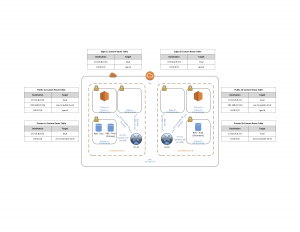
One part of my job is to work with our Client Services team to deploy hosted software solutions for customers. We accomplish this using Amazon Web Services (AWS) and a number of their cloud networking solutions. The base solution we have defined looks something like this:
- An AWS Virtual Private Cloud (VPC) is created for the customer in the specified AWS Region – for this example, we’ll say ‘us-east-1’ (N. Virginia). The subnet allocated to this VPC is from RFC1918 – we typically allocate a /21 (or larger).
- Within this VPC, 4 subnets are created which are spread across two Availability Zones (AZs). For this article, we’ll use ‘east-1a’ and ‘east-1b’. There are two private subnets which access the outside network via a NAT instance (or NAT gateway), and two public subnets which use an Internet Gateway (IGW) for outside reachability. Each subnet is a /24, and each AZ is allocated one private and one public subnet.
- AWS Relational Database Service (RDS) is often used for the application database. RDS is configured to use the private subnets, with one being primary and one being secondary/failover. We’ll say that east-1a is the primary subnet, and east-1b is the secondary.
- Customer Gateways (CGW), Virtual Gateways (VGW), and VPNs are created in the AWS console to support secure connectivity to the VPC from our company as well as from the customer. Customers may connect to RDS over an IPsec tunnel to create reports directly from the DB using the reporting tool of their choice.
We have successfully deployed a number of customers using this framework, and it has worked well. However, all customers have different requirements – and a new customer had a limitation that we had not dealt with before:
VPN connectivity is required, but no RFC1918 addresses may be used within the VPC. All addresses must come from the Public IP space.
This is the first in a series of posts describing how I arrived at a solution; hopefully these will help if you find yourself in a similar situation.
The following options were explored but were either not feasible or were not acceptable to the customer:
- Using IPv6 for addressing / connectivity
- Using the RFC6598 address space (100.64/10).
- Requesting that the customer dedicate part of their ARIN-assigned /16
- Obtaining a new IPv4 allocation from ARIN
- Purchasing IPv4 address space from a reseller
So, I recommended that we create a proof-of-concept to see if we could actually route Elastic IPs over an IPsec tunnel to the VPC. This would require finding a solution outside of the standard VPC VPN configuration, as there is a critical constraint which affects the customer requirement.
From https://aws.amazon.com/vpc/faqs/
Q. Can I assign one or more Elastic IP (EIP) addresses to VPC-based Amazon EC2 instances?
Yes, however, the EIP addresses will only be reachable from the Internet (not over the VPN connection). Each EIP address must be associated with a unique private IP address on the instance. EIP addresses should only be used on instances in subnets configured to route their traffic directly to the Internet gateway. EIPs cannot be used on instances in subnets configured to use a NAT gateway or a NAT instance to access the Internet. This is applicable only for IPv4. Amazon VPCs do not support EIPs for IPv6 at this time.
The POC was to use Cisco CSR 1000 instances in AWS to perform static NAT and to replace:
- The NAT instance
- The IGW
- The VGW
- The VPC VPN termination point
This would require configuring one CSR instance in east-1a and one CSR in east-1b as well as two additional subnets in the VPC (let’s call these subnets Edge-1a and Edge-1b). Each CSR is configured with three interfaces: one interface in the Edge subnet, one interface in the Public subnet, and one interface in the Private subnet. All traffic from each private subnet should use CSR private interface as the gateway. Traffic from the public subnets should use the CSR public interface for traffic destined to any 192.168.0.0 network (our company’s subnets) and should use the IGW for internet-bound traffic. The CSR edge interfaces must use the IGW for egress.
Before getting info the configuration details of the CSRs, let’s explore the initial VPC configuration to support this POC.
VPC Prefix: 172.16.8.0 /21
East-1a Config: Subnets:
Public-1a: 172.16.8.0 /24
Private-1a: 172.16.9.0 /24
Edge-1a: 172.16.12.0 /24
East-1a Config: Route Tables:
RTB Public-1a: 0.0.0.0/0 via VPC IGW. 192.168.0.0/16 via CSR-1a Public-1a interface
RTB Private-1a: 0.0.0.0/0 via CSR-1a Private-1a interface
RTB Edge-1a: 0.0.0.0/0 via VPC IGW
East-1b Config: Subnets
Subnet Public-1b: 172.16.10.0 /24
Subnet Private-1b: 172.16.11.0 /24
Subnet Edge-1b: 172.16.13.0 /24
(I know, the edge subnets aren’t contiguous… they were added after the VPC was configured, and I didn’t feel like rebuilding the environment and updating the diagrams for this post. Future deployments would use a slightly different subnet assignment, but the solution still works)
East-1b Config: Route Tables:
RTB Public-1b: 0.0.0.0/0 via VPC IGW. 192.168.0.0/16 via CSR-1b Public-1b interface.
RTB Private-1b: 0.0.0.0/0 via CSR-1b Private-1b interface.
RTB Edge-1b: 0.0.0.0/0 via VPC IGW
Important to remember is that the route tables contain an entry for the VPC prefix as a local address; that is, each route table has a ‘Local’ route to 172.16.8.0 /21. This understanding will be necessary when it comes time to configure high availability.
Elastic IP addresses allocated to the VPC (obfuscated; the actual EIPs are routable and not in the RFC1918 space):
Associated to instances / interfaces:
10.1.1.8: Associated with the csr-1a “edge” interface
10.2.2.16: Associated with the csr-1b “edge” interface
NOT associated with any instance but allocated to the VPC:
10.3.3.3: This will be used for the csr-1a Loopback1 interface.
10.4.4.64: This will be used for the csr-1b Loopback1 interface.
10.5.5.128: To be used for NAT to the RDS Test database (east-1a)
10.6.6.192: NAT to the RDS Production database – primary (east-1a)
10.6.6.224: NAT to RDS Production – secondary / failover (east-1b)
Now we have something that looks like this:

VPC Base Configuration with CSR 1000
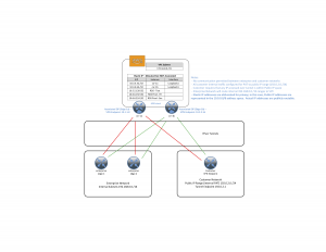
The CSR instances (“Security Max Performance”) will be configured to support Dynamic VTI IPsec (via FlexVPN). Our edge routers will each establish 2 tunnels – one to each CSR. Routing will be via BGP to the Loopback address. The customer will connect using a Fortinet device, with one tunnel to each CSR and use static routing. A simplified diagram is below:

VPC Diagram – Elastic IP and Tunnels
With the problem and proposed solution now defined, it’s time to start the fun part – configuration! That will be covered in the next post.